Host Systems
SPx Server is application software, designed to run on standard Intel PC or SBC hardware with Windows or Linux (see Spec tab). The software is simple to install.
Target Extraction
The SPx Extraction process examines the processed video to search for target-like returns that form a connected target-like shape. A set of configurable parameters define the target size of interest, allowing small noise returns or larger clutter or land masses to be eliminated early in the processing.
The extraction process begins by creating a set of spans that represent intervals of video above a threshold for each processed return. These spans are then combined across returns to form connected two-dimensional shapes. The weighted centre of gravity, bounding box and total weight of the plot shape are calculated and entered into a plot database, along with a timestamp. At this stage of the processing, no merging occurs of close plots that are likely to be derived from the same target. This allows partial plots to be reported on the network, if desired, and allows the tracking process to consider the merits of merging in the context of the local tracks.
Secondary Surveillance Radar Extraction
Interrogation mode tags may be embedded at the start of the IFF video stream as P1/P3 pulses or a specific mode specified, telling SPx Server which responses to expect. The processing includes de-FRUITING and de-garbling to remove typical noise from an IFF video.
The IFF video handling capabilities provide a viable, highly cost-effective alternative to traditional hardware-based IFF decoding systems.
Track Creation
The tracker maintains an active track database, updated with new plot data from the data extraction stage. New tracks are added automatically or from a manual request (operator input or external process).
The automatic track creation occurs when plots entered into the database are uncorrelated, or ungated, with any existing known target. A new preliminary track is created and is updated with future detections until confidence is established that the track is likely to be a target of interest.
The time a track is held in the preliminary stage is a programmable option and needs to be set to balance the speed of detection with the likelihood of a false alarm. In a low clutter environment, where extracted plots are likely derived from real targets, the acquisition time may be as short as 2 detections. For noisy situations, where the plot extractor is reporting false detections, the integration time in the preliminary stage may be extended.
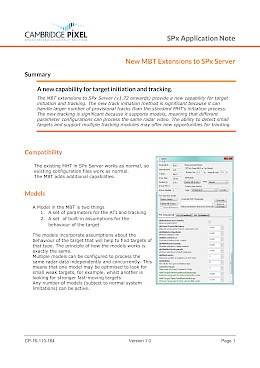
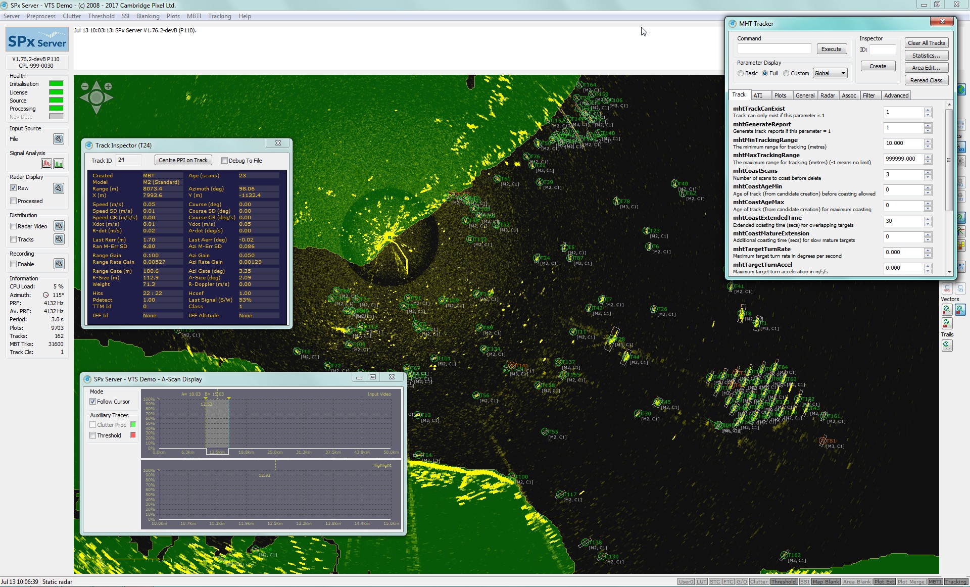
Model Based Tracking (MBT)
The MBT extensions to SPx Server (V1.72 onwards) can handle a larger number of provisional tracks than the standard MHT's initiation process. This allows specific target models to be created, meaning that different parameter configurations can process the same radar video. The ability to detect small targets and support multiple tracking modules may offer new opportunities for tracking. Click here for further details on the MBT extensions.
Track Filter
For each hypothesis, the tracker updates the current estimated position with the new measurement. If the measurement were known to be completely accurate, the update process would believe the measurement and the new estimate would be exactly the measured value. For various reasons, the measurement is inaccurate so the update process must take a weighted combination of the expected position and the measured position. This is the track filtering. SPx offers a number of track filtering modes. The simplest mode uses fixed gains in the components of the measurement. This can be successful for tracking applications where the target is clearly identified and relatively clutter free.
The filter works by computing a dynamic filter gain, K, based on estimated system noise and measurement noise models. The system noise is used to model uncertainty in the known dynamics of the target, including its ability to manoeuvre. As system noise increases, or equivalently as measurement noise decreases, the filter places more weight on the measurement so the filter gains increase. As system noise decreases or as measurement noise increases, the filter gains decreases causing less emphasis to be placed on the new measurement. The filter gains are continually changing and provide, under certain assumptions of the noise characteristics and linearity, an optimal estimation of the true target position.
Tracking Parameters
The tracking behaviour parameters may be set initially from a configuration file and may be adjusted during operation of the tracker using either a customer GUI or network interface. Parameters include:
- Min/max speed of target to be tracked
- Multi or single hypothesis association modes
- Fixed gain or adaptive gain
- Expected target dynamics
- Size limitations on targets to be tracked
- Measurement noise estimates
Redundant Operation
Dual instances can be run simultaneously to provide redundant operation for high reliability systems, with the secondary instance automatically taking over if the first instance fails, providing an uninterrupted stream of radar and target track data.
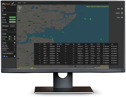
Additionally, SPx Fusion Server can support redundant operation, providing a consistent set of track IDs to clients in the event of failover, and SPx Monitor provides monitoring and diagnostics, showing which instance is active and automatically restarting applications that have stopped.
Three Versions Available
As standard, there are three main versions of SPx Server, each of which progressively adds additional processing functionality:
- SPx Distribution Server – includes primary radar digitisation and network streaming
- SPx Detection Server – adds both plot extraction and proximity detection processing
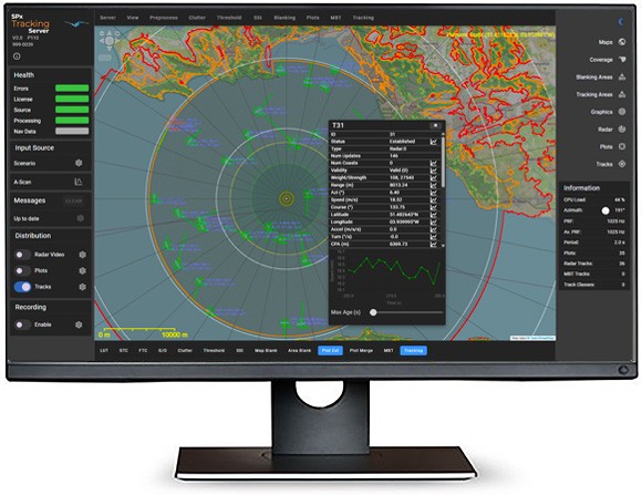
- SPx Tracking Server – offers a complete multi-hypothesis primary radar tracking solution
There are also embedded varitants of each optimised for the HPx-700 Radar Input and Processing Unit.
New Features Added
The latest version, SPx Server V2, includes new capabilities including:
- Proximity detection for collision avoidance and autonomous navigation
- Support for the HPx-700 embedded radar input and processing platform
- Output to TAK and SAPIENT track formats, supporting interoperability with modern Command and Control (C2) systems
- AI-assisted system configuration using Machine Learning to streamline setup and optimise processing parameters
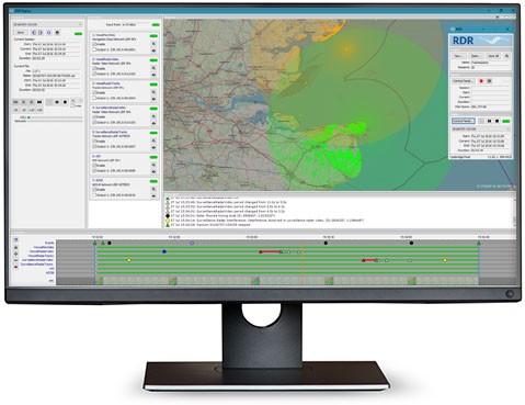
- Integrated radar coverage display for visibility validation
- Enhanced track reporting and plot history visualisation
- Configurable track labelling for clearer operator displays
- Multi-function primary and secondary (IFF) radar processor
- Radar video from HPx cards or network
- Radar processing
- Filtering
- CFAR Thresholding
- Area-based video filtering/masking
- Clutter map generation
- Plot Extraction and merging
- In-built AIS association
- AIS track display and recording
- Doppler Video support
- Multi-hypothesis target tracking
- Model-based tracking extension
- Fully configurable tracking
- Area-dependent tracking parameters
- Full auto track initiation
- Redundant operation, with automatic failover
- Built-in world coastline database
- Static or moving platform
- NMEA navigation input for ship systems
- Radar network distribution
- Radar, NMEA and AIS record/replay
- Comprehensive configuration GUI
- Web Interface for control and graphical monitoring
- Sidelobe suppression
- ARM support
- Windows or Linux versions
- Network remote control and API
- Receipt and tracking from plot data
- Receipt and distribution of lidar data
- Video, plot and track output to network
- Fully configurable for:
- Vessel traffic systems (VTS)
- Surface movement radars
- Air defence
- Security (personnel, vehicles etc.)
- Military naval
System Requirements
| Processor: | X86-64 architecture, or ARM v8-A or better (consult factory) Recommended processor is modern Intel Core i5 or higher / ARM Cortex-A72 or higher. Minimum 8GB system memory recommended. |
| Operating System: | Windows 11 Linux (Fedora, Ubuntu, RHEL) For other operating systems consult factory |
| Graphics: | Requires 1024 x 768 graphics display or higher for maintenance and configuration. Recommended PCIe or XMC graphics card. GUI is not needed for operational system. |
| Disk: | Disk storage is optional for radar video recording. |
| Network: | 100 Mbit or 1 Gbit Ethernet adaptor recommended. |
| Expansion Slot: | PCI, PCIe or PMC expansion slot required if using a HPx radar interface cards. Refer to the user manual for these cards for full details. |
Software Licensing
| Licensed Functions: | Radar video distribution |
| Plot extraction |
|
| Target extraction |
|
| Record and Replay |
|
| Moving platform |
|
| Licence Protection Method: | USB Dongle |
| MAC-address licence file | |
| (other schemes are possible, consult factory for details) |
Radar Interface
| Radar Input: | Hardware interface card: HPx200/200e/250/400e/346 |
| Network input from supported radar types |
|
| Radar Trigger: | PRF: up to 10kHz with HPx cards |
| Amplitude: Up to 30V. Single-ended (opto-coupled) or differential (RS422) |
|
| Impedance: 75R or high impedance |
|
| Radar Video: | Amplitude: 5V (positive or negative) |
| Impedance: 75R or high impedance |
|
| Azimuth - ACP/ARP: | Single ended signal up to 30V or differential RS422 |
ACP count: 60, 180, 300, 360, 1024, 2048, 4096, 8192, 16384 pulses per ARP. Software automatically detects ACP count. ACP Interpolation supported for low counts. |
|
ARP: 1 pulse per scan |
|
Rotation rate: up to 240rpm |
|
| Azimuth - Parallel: | 12 bit RS422 differential azimuth value with data strobe |
| Azimuth - Synchro/Resolver: | 115V reference voltage, 90V synchro (3 wire) or resolver (4 wire) input. Reference voltage is standard 115V input. (Other synchro voltages on request) Note: Synchro/resolver input requires use of HPx-180 synchro/resolver to parallel converter PCI card. |
| Plot Inputs: | Option to receive plot data from proprietary radars. Consult factory for details. |
Navigation Information
| Platform Navigation: | NMEA-0183 input GPRMC, GPHDT, GPHDM sentences used, interpreted by server. |
| Physical Interface: | Standard serial port on PC or single board computer |
| Network input (uses NMEA-0183 sentences in network packets) |
|
| Navigation Reporting: | Optional network distribution of NMEA sentences received on serial port |
| Programmable IP and port address for output |
|
| North Offset Adjustment: | Incoming azimuths may be ship or North referenced, with automatic conversion to North referenced from navigation data, as required. |
Performance
Video Processing with HPx Radar Interface cards
| Video Bandwidth: | 25 MHz (When used with HPx-200, HPx-200e or HPx-250 radar interface cards) |
| A-to-D Conversion: | Programmable 2 to 50 MHz sampling rate. 12-bit high-performance capture. Data is reduced to 8-bits through a programmable LUT. |
| Threshold Detection: | Adaptive threshold CFAR technique with geographical area thresholding |
| Clutter Processing: | Software-based scan-to-scan correlation |
| Clutter subtraction |
|
| Land mass blanking |
Processing
| Land Mask: | Static mask: complex polygon of any shape or size, optionally containing holes. |
| World vector shoreline: land masking using built-in database of world shoreline data (static or moving platforms supported). |
|
| Polygon set is defined in world x,y coordinates and is automatically converted into polar space. Typical azimuth resolution is 0.18 degree and range resolution matches input data resolution. |
|
| Area Dependent Processing: | Tracker parameters can be assigned different values in different areas (static platforms only). |
| Polygon set is defined in world x,y coordinates and is automatically converted into polar space. Typical azimuth resolution is 0.18 degree and range resolution matches input data resolution. |
|
| Automatic Initiation Areas (ATI): | Static mask. Complex polygons defined in x,y coordinates. Can be any shape or size. |
| Independent areas can be configured for radar processing, track initiation and tracking. |
|
| Optional automatic suppression of plots over land areas using world vector shoreline database (supplied as standard). |
|
| Plot Extraction: | Configurable plot geometry (min/max range and azimuth) |
| Optional plot merging (multiple modes) |
Digital Video Distribution
| Network Distribution: | Distribution onto LAN of radar video data in polar format |
| Compression: | ZLIB or ORC (Open Radar Coding) |
| Data Rates: | Highly dependent on input data and configured resolution. |
| Typical figures from 2 Mbits/sec for processed video to 10 Mbits/sec. |
|
| Network Protocol: | UDP - Unicast or Multicast distribution |
| Video Store for Distribution: | Raw input data |
| Processed data |
|
| Clutter map |
|
| (One of above with standard server. Multiple channels of distribution are supported with customised server variants, including options for multi-resolution data) |
Target Tracking
| Maximum number of targets: | 500 (typical, but not limited by software) |
| Track Initiation: | Automatic, with programmable extraction areas defined as polygons or range-azimuth segments (static radar only) |
| Automatic wake area elimination (configurable geometry) |
|
| Shadow area elimination from known targets |
|
| Manual track initiation from remote system |
|
| Configurable min/max initiation speeds, which may be area dependent |
|
| Max initiation speed: 1000 m/s |
|
| Minimum initiation range at maximum speed: 10NM for targets moving tangential to radar 3 NM for targets moving radially towards or away from radar |
|
| Programmable initiation time from 2 scans upwards using M:N or SPRT integrator. Initiation criteria may be area dependent. |
|
| Signal to Clutter: | Typically 8 dB or higher expected |
| Target Speeds: | Programmable minimum and maximum target speed for initiation in the range 0 to 1000 m/s |
| Programmable minimum and maximum target speed for tracking in the range 0 to 1000 m/s |
|
| Tracking Performance: | Figures are highly dependent on sensor, operating conditions and configuration data. |
| Sample configuration - sea state 1, 100m2 RCS target: |
|
For radar range 200NM, target at 100 NM
|
|
For radar range 70NM, target at 35NM
|
|
For radar range 35NM, target at 18NM
|
|
| Notes: Performance figures are typical, but depend on exact characteristics of radar and target. Target assumed to be moving in straight line. If server is applying North offset compensation, timely updates of ship's heading are critical for good tracking performance. Quoted values of σ are standard deviations of errors. |