
What is radar video latency?
In the case of radar video, latency is the time it takes for data to go from the radar source to a display screen. Radar video latency is typically measured in milliseconds and the closer it is to zero the better.
Why measure it?
A large latency could result in a noticeable difference between the radar antenna rotation and its representation on the screen. The true position of targets may have changed significantly by the time they are drawn on the screen. Here at Cambridge Pixel our engineers are occasionally asked: “How can I measure the latency between receipt of a radar video signal into an HPx card(our hardware for interfacing to analogue radar video signals) and its presentation on a display?” The answer to this depends on a number of considerations:
- The acquisition and input buffering within the HPx hardware
- Processing and packetisation within the sending software
- Network delays
- Scan conversion buffering and refresh timing
Thinking about each of these stages, in broad terms one might expect 40ms of latency at the analogue acquisition and buffering stage, followed by a few milliseconds of processing latency, some non-deterministic network latency (maybe 5ms), and finally about 30ms of latency at the scan conversion end. These numbers combine to give a total of around 80ms, from receipt of data at the HPx card to appearing on the client screen.
In most situations it is reasonable to assume a latency of around 100ms as a good working value. However, there are occasionally times when you may actually need to measure the latency. For example, to demonstrate compliance against a specified requirement or to ensure correct operation of some downstream system.
Our method for measuring latency
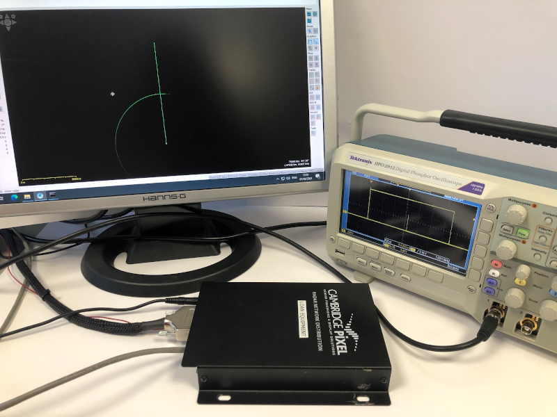
By using a suitable test source, an oscilloscope and a video camera it is possible to get a reasonable estimate for the end-to-end latency. In Cambridge Pixel’s laboratory, we built up a test system using an HPx-300 card as the source of radar signals, feeding into an HPx-346 unit. The HPx-300 card is Cambridge Pixel’s hardware card for generating analogue radar signals, based on data provided in software. The HPx-346 handles both the acquisition and distribution of radar video data.
Step-by-step
- The HPx-300 card is driven with a special test pattern, providing a single strobe pulse at 0 degrees azimuth, generating a clear reference mark on the oscilloscope and on the computer display.
- An instance of SPx Server is also run on the client PC, to provide the scan conversion and display of the received radar video data.
- The video signal from the HPx-300 card is passed into an oscilloscope. The oscilloscope display and PC display are both captured within the same video camera feed.
- By stepping through the recording of the oscilloscope and PC display, frame-by-frame, it is then possible to measure the time between the strobe pulse first appearing on the oscilloscope and then on the PC screen. This time delay is the latency that we're looking for.
The results
When we ran this test in our lab, the measured latency was...
Subscribe to continue reading this article, it's free.
Free access to Engineering Insights, authored by our industry leading experts.
You will also receive the Cambridge Pixel newsletter which includes the latest Engineering Insights releases.
Fill in the form below and you will be sent an Instant Access link.