
Insights Article
When connecting an interface card (for example one of Cambridge Pixel’s HPx series of cards) to a radar or simulator, the possibility arises of ground loops. These can introduce noise into the signals, but more seriously they can permit large currents to flow into sensitive devices causing card failure (on either the sender or receiver side). This article explains the issues and describes the best practice for connections.
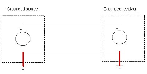
There are typically several signals associated with a radar interface and these signals may be of different types. The specific situation that needs careful consideration is when a grounded signal source is used with a grounded signal receiver. The situation is shown below. The ground connection on the source and receiver is shown in red. In this configuration, the signal from the source has its negative side connected to the chassis ground. On the receiver, the negative input is also connected to chassis ground. The two separate ground points provides a path for spurious currents through induced voltages in the cable connecting the negative signals, and also in the ground path of each side.
The signal being shown here could be video, trigger, ACP or ARP (or any other signal being used). It is the same consideration for each signal. Each one needs to be considered separately.
-
• Video
The radar video inputs to the HPx card are always single ended with the negative connected to ground, and hence the chassis. Therefore, if the source of the radar video signal is also grounded (as in the above diagram) the double grounded situation arises.
-
• Trigger, ACP and ARP
If RS422 (differential) connections are used, there is no grounding issue.
If opto-coupled connections are used, there is no grounding issue.
If programmable threshold input is used, the negative input is connected to chassis ground.
Therefore if the source of the signal is also grounded, the double grounded situation arises.
The grounding situation in the source
It will typically not be documented whether the source output is isolated or grounded. A simple test is to measure the impedance from the negative output to the chassis ground. If this is 1 Ohm or less, then the negative output is likely grounded...
What to do if both the source and the receiver are grounded
If it is established that the source and the receiver for a signal are both grounded, then further consideration is needed....
Subscribe to continue reading this article, it's free.
Free access to Engineering Insights, authored by our industry leading experts.
You will also receive the Cambridge Pixel newsletter which includes the latest Engineering Insights releases.
Fill in the form below and you will be sent an Instant Access link.