The development of radar displays and radar processing for maritime navigation systems is subject to minimal performance requirements defined by IEC 62388 (Edition 2.0). This document defines requirements for equipment, including radars and AIS, as well as defining methods of validating performance of software products that process data to generate displays or navigation information. In this paper we consider specifically how radar processing products, especially radar tracking systems, can be validated against the IMO requirements.
Software Testing
One of the challenges for a software developer creating applications for radar processing is that it is difficult to obtain access to radar data for testing. A final deployment of a system on board a ship with real radar connected is too late in the process for reliable verification testing. Also, it does not provide a basis for controlled regression testing which is essential for high-quality software development. In regression testing, a set of tests will confirm the operation of the software with a well-known set of inputs, verifying that the output is as expected. Those tests can then be performed continually, and ideally automatically, as the software is developed ensuring that future changes do not affect the established behaviour.
Regression testing is an established technique for checking the correctness of software in the face of changes. It is not easy to develop the infrastructure to support it and write the test code, but it is an essential step in maintaining high-quality software over the lifetime of a software product. Many of the horror stories we read about concerning botched software releases are due to poor investment in regression testing. It is interesting to note that it is not unusual for the costs of developing the test software to exceed the costs of thedevelopment the application itself, so it is very much an investment in long-term quality assurance.
A software application for maritime applications will typically run on a PC or embedded computer and comprise several components. The most visible of these will be the user-interface that provides a display of information to the mariner, as well as supporting interactions to change modes or provide requested information. Many of the requirements set out in IEC 62388 define requirements of the user-interface. This is intended to provide some consistency across displays from different manufacturers, without affecting the ability of different commercial products to differentiate themselves. The emphasis being on what should be displayed more than where or how something should be displayed. The behaviour of the software is expected to provide a set of essential display capabilities and processing functions that the mariner needs for navigation.
Verification of Tracking Performance
IEC 62388 defines the behaviour of a radar processor concerned with automatic detection and maintenance of targets from radar. This means processing the radar video to identify targets of interest, whilst being resilient to clutter that might generate false targets. The goal is to reliably generate new targets as quickly as possible, without generating false alarms.
The IEC 62388 specification defines the expected tracking accuracy after initial acquisition, including the speed and course accuracy after 1 minute (the trend) and the results after 3 minutes (the prediction). To verify that the radar processor is performing to these standards it is necessary to provide a source of radar data as an input. It would of course be possible to create a scenario with real targets observed from a real radar connected to the radar processor. However, this would be cost-prohibitive and impractical for system testing. Nor would it support the requirement for regression testing that would confirm that the system works today just as well as it worked yesterday.
What is required is a simulator to generate representative sets of data that resemble the real radar data. Additionally, it is required that the simulated data be repeatable and able to be automated so that the same test can be easily re-run.
Radar Simulation
A radar simulator needs to generate data that is close to the format and content of the data that would be seen from a real radar. With this in place, it is possible to create controlled scenarios with moving targets, moving own-ship and different characteristics of the radar. Provided the behaviour of the simulator sufficiently represents the behaviour of the real radar, the simulator will become the test bed for verifying that the processing performance meets essential minimums (e.g. IEC 62388) and exploring the limitations to characterise performance.
Getting the content of the radar video to resemble the real radar is key. This includes realistic appearance of targets, noise, clutter and land returns. The simulated radar must be generated in a form that is consistent with the radar, ie as a discrete number of returns (defined by the PRF of the radar) generated over a fixed rotation period (the scan speed). Commercial navigation radars (for example from Simrad, Furuno, Raymarine etc) typically generate their video as network packets in a proprietary format These are simply different network formats of what is essentially the same structure of data. It isn't so important that a simulator can generate each of these formats, and using a neutral format such as ASTERIX CAT 240 is generally preferable. Of course, this assumes that the radar processor under test can accept this format as input.
With a Simulator creating specific scenarios of moving targets, the output of the radar processor must be examined to verify that the performance is as expected. This could be done by inspection. The Simulator would be started to create the desired input data and the output of the radar processor would be observed to confirm that tracks are being created and the errors in those tracks (speed, course, position etc) are within limits. Although possible if each test was to be run just once, the manual verification method is tedious and does not lend itself to automated regression testing. The desired solution is an automated process that examines the output tracks of the radar processor under test and compares the values to the desired numbers. If there are discrepancies, these can be reported or logged. With such an automated system in place, the tests can be re-run easily at minimal cost. As the radar processor product development proceeds, the continuous re-testing validates performance and if a non-conformance is observed it can be associated with the most recent software changes. The burden of extensive retesting at each software releases is significantly reduced by this approach, enabling new software releases to be provided more quickly and with less risk.
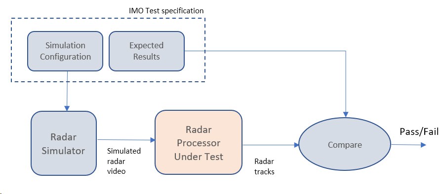
Figure 1 shows this process. Each radar test is defined by a combination of a simulation configuration, which defines the movement of targets and own-ship for the test, and an expected set of results in terms of track dynamics. The Expected Results file defines bounds on the error in a track report as a function of time. The observed track reports are compared with the expected results to generate an automatic pass/fail for each test.
IMO Tracker Scenarios
In this section we consider the specifics of the IMO "Target motion and tracking accuracy" requirements as defined in Section 11.3.14 of IEC 62388 Edition 2.0 (2013). There are 5 scenarios defined in the document, each for normal and high-speed targets. Considering scenario 1 as an example, the normal speed test is defined by the following own-ship and target details:
⦁ Own ship moving at 20 kn due North
⦁ Target 1 moving at 28.3 Kn on a course of 45 degrees with a start range of 9.5 NM from own ship at a bearing of 270 degrees.
⦁ Target 2 moving at 22.4 Kn on a course of 27 degrees with a start range of 1.12 NM from own ship at a bearing of 333 degrees.
⦁ Target 3 moving at 15.3 Kn on a course of 293 degrees with a start range of 9.25 NM from own ship at a bearing of 45 degrees.
⦁ Errors are added to the radar targets to simulate sensor errors (specification of the errors is defined in IEC 62388 but not reproduced here).
The simulation files need to define the initial position of own ship and each of the three test targets. They then define the motion for own-ship and the targets which affects the observed radar positions over time. Given the calculated true-world positions at each moment in time, the simulation process adds noise to simulate radar measurement errors, and finally outputs a radar sweep as a real-time data stream comprising the target video. The sweep rate and PRF of the radar are configurable parameters.
The output radar video data (for example in ASTERIX CAT-240 format) then goes into the radar processor under test. The radar processor is then receiving a data stream of video that is very similar to that expected from the real radar. The timing of the data stream is based to the timing of a typical radar, simulating discrete radar returns and scan rate. The radar processor is required to extract tracks and output these, for example in ASTERIX CAT 48 format. A new track message is generated once per radar sweep, and this information is captured by a Comparison stage, which compares the reported track information with the expected information held in the "Expected Results" configuration file. The Expected Results file defines the expected track position, speed and course at different times - effectively the ground truth - as well as the permitted errors in the observed values. The Comparison module examines the difference between the reported and desired values and compares this to the permitted margin of error. There will always be some error between the true values and the reported ones, for example arising from the noise that was injected into the sensor data during the simulation. The effect of this noise will be larger soon after initial acquisition, but the effects of filtering over time will slowly reduce the effects of noise and allow the estimated values to become close to the ground truth.
The Comparison module is able to report a pass or fail of each test. Because each test is fully automated, the tests can be run without supervision.
Subscribe to continue reading this article, it's free.
Free access to Engineering Insights, authored by our industry leading experts.
You will also receive the Cambridge Pixel newsletter which includes the latest Engineering Insights releases.
Fill in the form below and you will be sent an Instant Access link.