



When a ship rolls or pitches, the uncompensated radar antenna tilts out of the Earth’s horizontal plane. Since the radar measures target directions relative to its own tilted deck plane rather than the horizon, this tilt rotates the radar’s internal coordinate system. For surface targets, this dynamic tilt creates an apparent bearing shift, making a target appear at a slightly different angle on the radar screen compared to its true direction over the water.
As the roll and pitch change, so too does this apparent shift, modulating the position of target returns within the radar video and potentially causing tracking problems.
The Core Geometry
Assuming it has not been mechanically stabilised, a marine radar sweeps a 360° circle aligned with the ship’s deck. When the ship is level, the deck plane matches the Earth horizontal plane. A target’s bearing relative to the ship will be the same in the deck (radar) plane and the Earth plane.
When the vessel rolls and/or pitches:
- The Rotated Reference Frame: The radar antenna’s rotational axis tilts away from true vertical.
- Line-of-Sight Projection: Target detections in the Earth horizontal plane are projected onto the tilted deck (radar) plane.
- Apparent Azimuth Shift: The target’s bearing is unaffected within the Earth plane, but the angle between the ship’s bow and the target changes within the rotated deck coordinate frame.
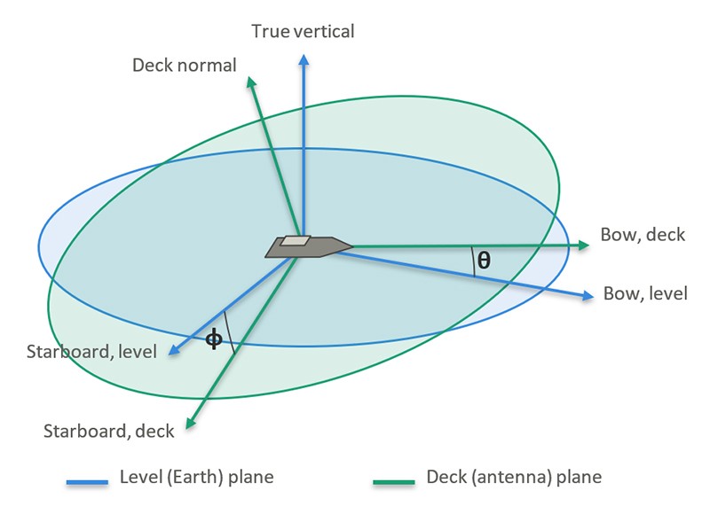
Shown with roll φ = 15° (starboard down) and pitch θ = 10° (bow up)
From a target detection perspective, the apparent change in target bearing is significant. A target with a true Earth bearing (β) relative to the ship will present a radar bearing (α) that varies as a function of the roll, pitch and true bearing.
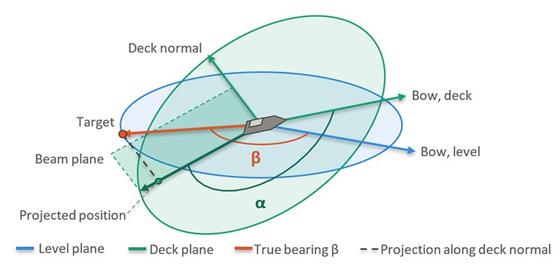
Exaggerated: roll φ = 30°, pitch θ = 20°; a target at β = 145° is seen by the antenna at α ≈ 155°
How Vessel Motion Alters Bearing
The equation mapping the true bearing (β), roll (φ) and pitch (θ) to an apparent bearing (α) is given as:
tan(α) = (sin(β).cos(φ) + cos(β).sin(θ).sin(φ)) / cos(β).cos(θ) [1]
Conversely, to calculate the true bearing, given the apparent bearing (i.e. measured by the radar) the equation is:
tan(β) = (sin(α).cos(θ) − cos(α).sin(θ).sin(φ)) / cos(α).cos(φ) [2]
These equations are simplifications, assuming that radar and target heights are ignored.
The apparent bearing shift depends on which way the vessel tilts relative to the target:
- Pure Roll Motion (Side-to-Side Tilt):
- Has the zero impact on targets directly ahead (Bow) or behind (Stern). Rolling tilts the antenna along the line of the vessel.
- Has zero impact on targets directly off the port or starboard beams. Rolling tilts the antenna up/down at the 090° and 270° bearing angles. Targets will be detected in upper or lower part of the radar beam, without changing their azimuth.
- Pure Pitch Motion (Fore-and-Aft Tilt):
- Is equivalent to pure roll motion but tilts the antenna in the axis across the vessel instead.
- Has zero impact on targets directly ahead or behind, to starboard or port. Targets to port or starboard are unaffected and those ahead or astern are detected higher or lower in the radar vertical beam but still on the same bearing.
- Combined Roll and Pitch:
- When a ship rolls and pitches simultaneously, there is an apparent bearing shift for targets dead ahead and astern. This arises from the cross term of roll and pitch (sin(θ).sin(φ)) in the equations above.
- Targets directly off the port or starboard beams remain unaffected. It can be shown that when the true bearing (β) is 90° (or 270°) equation [1] reduces to:
tan(α) = ∞
which implies α = β = 90°, independent of roll or pitch angle.
Impact Analysis
The table below shows some representative bearing errors, for bearings of 0°, 45°, 90° and 135°, under different roll and pitch conditions.
| Case | Angle | β = 0° | β = 45° | β = 90° | β = 135° |
|---|---|---|---|---|---|
| Roll only (φ) | 5° | 0.00 | −0.11 | 0.00 | +0.11 |
| 10° | 0.00 | −0.44 | 0.00 | +0.44 | |
| 20° | 0.00 | −1.78 | 0.00 | +1.78 | |
| 30° | 0.00 | −4.11 | 0.00 | +4.11 | |
| Pitch only (θ) | 5° | 0.00 | +0.11 | 0.00 | −0.11 |
| 10° | 0.00 | +0.44 | 0.00 | −0.44 | |
| 20° | 0.00 | +1.78 | 0.00 | −1.78 | |
| 30° | 0.00 | +4.11 | 0.00 | −4.11 | |
| Roll and pitch (φ = θ) | 5° | +0.44 | +0.22 | 0.00 | +0.22 |
| 10° | +1.75 | +0.86 | 0.00 | +0.89 | |
| 20° | +7.10 | +3.35 | 0.00 | +3.80 | |
| 30° | +16.10 | +7.19 | 0.00 | +9.57 |
Table 1: Sample Azimuth Error Values, Calculated for Different Roll and Pitch Combinations
Even quite modest roll and pitch angles (up to 10°) can yield significant apparent changes in radar bearing, up to nearly 2° if the pitch and roll coincide.
Notes. Errors are computed exactly from tan(α) = (sin(β).cos(φ) + cos(β).sin(θ).sin(φ)) / cos(β).cos(θ), based on pitch θ of the bow axis above the horizontal, and then roll φ about that pitched bow axis, with positive roll starboard down and positive pitch bow up. A positive error means the antenna reads the target clockwise of its true bearing.
The following plot shows typical, asynchronous roll and pitch behaviour.
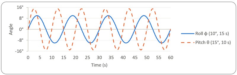
Given the roll and pitch behaviour above, the time-varying bearing error at selected target bearings would be as shown below.
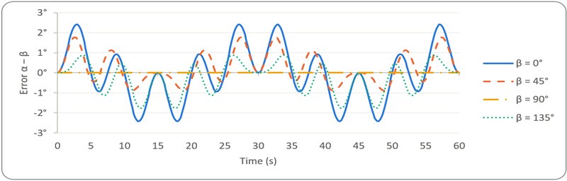
If left uncorrected, the video returns for targets on successive radar sweeps may occur on quite different bearings. For example, with reference to the graph above, if a target is on a true bearing of 0° degrees (i.e. dead ahead) and is first observed by the radar at a time of 9 seconds and then again at 12 seconds, its apparent bearing will have shifted by more that 3° between these measurements. This is obviously significant from a target tracking perspective.
Subscribe to continue reading this article, it's free.
Free access to Engineering Insights, authored by our industry leading experts.
You will also receive the Cambridge Pixel newsletter which includes the latest Engineering Insights releases.
Fill in the form below and you will be sent an Instant Access link.

 Meet us at: